|
|
|
Attenuators (my own explaination)
A simple free calculator for attenuators made by excel is available by clicking HERE
Attenuators are used to adjust signal levels, to control impedance mismatch, and to isolate circuit stages. Important attenuator properties are attenuation flatness vs frequency, VSWR, and power-handling capability. The familiar pi-circuit and T-circuit attenuator topologies are shown in figure 1 and Figure 4.
An attenuator circuit allows a known source of power to be reduced by a predetermined factor usually expressed as decibels. A powerful advantage of an attenuator is since it is made from non-inductive resistors, the attenuator is able to change a source or load, which might be reactive, into one which is well known and resistive. This power reduction is achieved by the attenuator without introducing distortion.
Shown in figure 1 below is the most common attenuator circuit known as the
"pi attenuator network". Included in this figure there are the formulas to
calculate the required resistances R1 and R2. figure 1. - pi attenuator network schematic and formula for equal impedances
Note the above formulas are for equal source and load impedances of whatever value.
The factor K is called the ratio of current, voltage, or power corresponding to a given value of attenuation "A" expressed in decibels. It is the more difficult calculation which proceeds as follows: "K"
is the number 10 raised to the power of the value of attenuation "A" in dB,
divided by 20. K
= 10 ("A" / 20) As
just one practical example, let's look at 3 dB attenuation and calculate our "K"
factor. K = 10 (3 / 20) = 10 (0.15) = 1.4125 Resistor values for a 50 ohm pi attenuator - equal source and load
Perhaps the most common use of an attenuator is in 50 ohm radio circuits. For this purpose I have included a small table in figure 2 below which depicts common power reduction values of 3 db, 6 dB, 10 dB and 20 dB. Please refer to figure 1 schematic.
figure 2. - Resistor values for a 50 ohm pi attenuator network - equal source and load
Under the columns of "actual" I have included resistors from the E24 series of resistor values. For most practical purposes these values will suffice.
If, as I suggest you reviewed the topic decibels you would know that decibel values add together.
A practical example of a pi attenuator
Assume we have a 50 ohm amateur transmitter with an output power of five watts. We want to reduce that power down to 250 milli-watts. This means we must reduce the power by 4.75 watts.
This power reduction MUST be dissipated in our pi network attenuator. This is a very important point to keep in mind, I will tell you later as to why.
By simple calculation we know that this is 4.75 / 5.0 = .95 or a 95% reduction in power.
Looked at in another way all we want is 5% of the original power or 1 /20th. On my calculator 5% is expressed as .05 and log .05 = 1.301 which from our tutorial on decibels we know to multiply by 10 because we are dealing in power levels. This means we're looking for a power reduction of 13 dB.
Using the formula in figure 1 we will now construct a 13 dB "pi network attenuator" designed for equal source and load impedances of 50 ohms.
Calculating a practical example of a 13 db pi network attenuator
We start by determining our "K" factor for 13 dB.
K = 10 (13 dB / 20) = 10 (0.65) = 4.4668
Determine R1 where (K + 1) = 4.4668 + 1 = 5.4668 and (K - 1) = 4.4668 - 1 = 3.4668 and (K + 1) / (K -1) = 5.4668 / 3.4668 = 1.5769
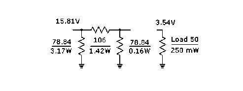
As you can see these mathematics are "real" hard. We multiply this answer 1.5769 by our impedance "Z" which is, 1.5769 X 50 = 78.84 ohms for R1. This is depicted in figure 3 below
figure 3. - A practical example of a pi attenuator at work
Now we calculate R2 and again our "K" value for a 13 dB attenuator remains at 4.4668
First we take the square of "K" which of course is 19.95, subtract 1 = 18.95, then divide by "K". This becomes 18.95 / 4.4668 = 4.24
This figure is then multiplied by our impedance "Z" which has been divided by two. In our case we get 4.24 X (50 / 2) = 106 ohms. Now could I make anything simpler to follow?
Calculating unequal impedance pi-attenuators
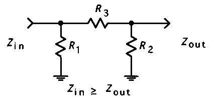
A more generic topology of a pi-attenuator is shown below
The related formulas to calculate the three resistors are more complex with respect to the same topology but with equal impedance, in this case they are
where: Zin = desired
input resistance (ohm) Zout = desired output resistance (ohm) A = transducer loss (dB) Minimum loss that can be achieved for given Zin and
Zout
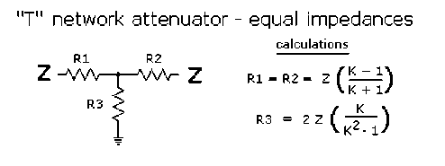
T network attenuator
This attenuator network is somewhat different with respect to the previous pi type. Notice the different but somewhat similar calculations. Anyway, I've sometimes used this topology, and beyond that.
figure 4. - "T" network attenuator
For me the calculations are no more difficult or easier than the pi network attenuator. Anyway I have included a small table below which depicts common power reduction values of a “T” attenuator of 3 db, 6 dB, 10 dB and 20 dB. Please refer to figure 4 schematic.
Calculating unequal impedance T-attenuators
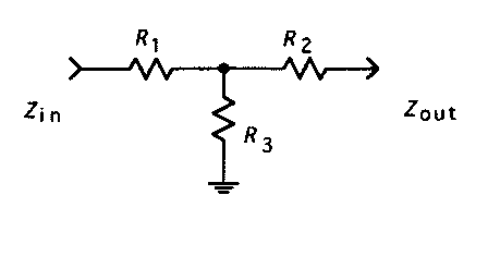
A more generic topology of a T-attenuator is shown below
The related formulas are shown below:
where: Zin = desired
input resistance (ohm) Zout = desired output resistance (ohm) A = transducer loss (dB) Minimum loss that can be achieved for given Zin and
Zout
Summarising attenuators 1.
Complete your calculations of resistor values in a methodical manner
and double check them. 2.
Do take power dissipation into account. Allow a good safety margin.
3.
Use non-inductive resistors for RF
applications 4.
If sufficient demand exists I will present a paper on designing
attenuators for unequal terminations. 5. We discussed the "pi" and "T" type attenuators here. Among others, there are the "H", "L", "O" and "U", bridge types, balanced and unbalanced types, ladder types and even attenuators using potentiometers (audio). The bridged-T attenuator
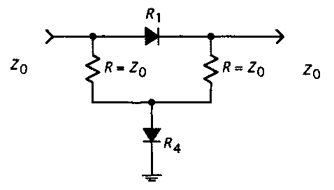
The bridged-T topology is frequently used with PIN diode electronically controlled attenuators, as shown in figures 5, because only two diodes need to be controlled (as opposed to three with the T-circuit or pi-circuit configuration). Variable attenuators using PIN diodes can be designed to have less intercept-point variation with attenuation setting than a functionally comparable transistor automatic gain control (AGC) stage
figure 5. – Variable attenuator using PIN diodes A schematic example of a FM power attenuator is available by clicking HERE A schematic example of an UHF overdrive limiter is available by clicking HERE
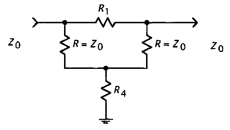
figure 6. – Bridged “T” topology
To calculate the Bridged “T” network a set of more simple formulas can be used, they are reported below (please refer to figure 6)
Bridged T component values: where:
A = desired attenuation loss (dB) Z0 = terminating system impedance (ohm)
That's all, enjoy for it!! ;-) Carlo
You are here: Home-Training and courses-Attenuators Previous Topic: Radici cubiche Next Topic: Chua circuit
|


